Configuring EtherChannel and 802.1Q Trunking
This page will give you a quick summary of configuring etherchannels. Etherchannels provides fault-tolerant high-speed links between servers, switches and routers. With etherchannels you can increase the bandwidth of an infrastructure port for example. Etherchannels are highly recommended in a data center environment, were you have active-active (dual homed) server connections to the edge. In a Nexus vPC design you be bound to use Etherchannels and be familiar with the configuration of it.
Etherchannel provides a load-balance algorithm between to physical lines. An etherchannel consists of individual
Gigabit – or Fast Ethernet links bundled into a single logical link.
Given the following figure
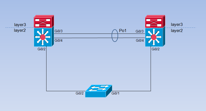
1. Understanding Port-Channel Interfaces
If a link within a port-channel fails, the remaining physical links overstrains the traffic and a trap is send
for a failure, identifying the switch and the appropriate port.
- Layer 3 interface – i never see such a configuration in an enterprise environment.
I don’t know if there is a differences between Layer 2 and Layer 3 logical port-channels.
If somebody know the differences, please provide me with a clarification of fact.
At a layer 3 interface you have to create the port-channel manually with the gloabel
command interface port-channel … - Layer2 interface – the logical port-channel will be automatically created.
2. Understanding the Port Aggregation Protocol and Link Aggregation Conrol Protocol
Port-channel can be created with 2 different protocols.
PAgP (Port Aggregation Protocol – cisco proprietary)
LACP (link Aggregation Control Protocol – non cisco proprietary)
LACP is defined in IEEE 802.3AD and allows Cisco switches to manage Ethernet channels between switches that conform to the 802.3AD protocol
3. Table of different Port-channel Modes
| Mode | Description |
| active | Places an interface into an active negotiating state, in which the interface starts negotiations with other interfaces by sending LACP packets. |
| auto | Places an interface into a passive negotiating state, in which the interface responds to PAgP packets it receives but does not start PAgP packet negotiation. This setting minimizes the transmission of PAgP packets. |
| desirable | Places an interface into an active negotiating state, in which the interface starts negotiations with other interfaces by sending PAgP packets. |
| on | Forces the interface into an EtherChannel without PAgP or LACP. With the on mode, a usable EtherChannel exists only when an interface group in the on mode is connected to another interface group in the on mode. |
| passive | Places an interface into a passive negotiating state, in which the interface responds to LACP packets that it receives, but does not start LACP packet negotiation. This setting minimizes the transmission of LACP packets. |
4. Exchanging PAgP Packets
With the use of the protocol PAgP you have two possible modes. Auto and desirable.
- An interface in the desirable mode can form an EtherChannel with another interface that is in the desirable or auto mode.
- An interface in the auto mode can form an EtherChannel with another interface in the desirable mode.
- An interface in the auto mode cannot form an EtherChannel with another interface that is also in the auto mode because neither interface starts PAgP negotiation.
5. Exchanging LACP Packets
With the use of the protocol LACP you have also to possible modes. active and passive.
- An interface in the active mode can form an EtherChannel with another interface that is in the active or passive mode.
- An interface in the active mode can form an EtherChannel with another interface in the passive mode.
- An interface in the passive mode cannot form an EtherChannel with another interface that is also in the passive mode because neither interface starts LACP negotiation.
6. Understanding Load Balancing and Forwarding Methods on a Catalyst 6k
A hashing function is a map with a big input amount (key amount) that maps to a
smaller destination amount (hash value). Hence source and destination ip will be
send to the Switch Processor (SP). The SP calculates the hash algorithm. This is commonly called the
Result Bundle Hash (RBH).
The Cisco-proprietary hash algorithm computes a value from 0 to 7. (RBH 0x0 – 0x7)
With this value as a basis, a particular port in the Etherchannel is chosen.
The port setup includes a mask which indicates which values the port accepts for transmission.
With the maximum number of eight ports in a single Etherchannel, each port accepts only one value.
If the Etherchannel has four ports, each port accepts two RBH values, and so on.
6.1 Ratio list for port-channels
| Number of Ports in the EtherChannel | Load Balancing |
| 8 | 1:1:1:1:1:1:1:1 |
| 7 | 2:1:1:1:1:1:1 |
| 6 | 2:2:1:1:1:1 |
| 5 | 2:2:2:1:1 |
| 4 | 2:2:2:2 |
| 3 | 3:3:2 |
| 2 | 4:4 |
Note: The hash algorithm cannot be configured or changed to load balance the traffic among the ports in an EtherChannel.
Note: The same Cisco-proprietary hash algorithm is also implemented in Cisco Catalyst 6500/6000 Series Switches that run Cisco IOS software.
Hence, in essence, you can only achieve perfect load balancing, even with random addresses, if you have two, four, or eight ports in the port channel.
For a 6500 Catalyst switch hardware with a Policy Feature Card 3 found on the Sup720 –
the hash algorithm uses a 3-bit hash. So you have 8 possible RBHs (called buckets)
that chooses the physical ports.
for example:
For a two port Ether-channel you have 2 buckets for each port.
For a four port Etherc-channel you have 4 buckets for each port.
Since the hash algorithm is calculated by hardware, some switches and feature cards uses
a 8-bit hash algorithm. So the result is not the same as shown in Table 3.
Anyway i would recommend to use not odd port-channels. Use even port-channels to
ensure an evenly distributed traffic on each physical ports.
2,4, or 8.
6.2 Traffic distribution for a 3 bit hash
Table 3
| Bundle | Link1 | Link2 | Link3 | Link4 | Link5 | Link6 | Link7 | Link8 |
| 8 | 12,5% | 12,5% | 12,5% | 12,5% | 12,5% | 12,5% | 12,5% | 12,5% |
| 7 | 25% | 12,5% | 12,5% | 12,5% | 12,5% | 12,5% | 12,5% | |
| 6 | 25% | 25% | 12,5% | 12,5% | 12,5% | 12,5% | ||
| 5 | 25% | 25% | 25% | 12,5% | 12,5% | |||
| 4 | 25% | 25% | 25% | 25% | ||||
| 3 | 37,5% | 37,5% | 25% | |||||
| 2 | 50% | 50% |
7. To see what the ‘load’ value is for a 2 and 4 port channel!
+++++++++++++ Po1 ++++++++++++++++++++++
Cat_6509-sp#sh interfaces port-channel 1 etherchannel
Port-channel1 (Primary aggregator)
Age of the Port-channel = 188d:02h:40m:22s
Logical slot/port = 14/1 Number of ports = 2
HotStandBy port = null
Port state = Port-channel Ag-Inuse
Protocol = LACP
Fast-switchover = disabled
Load share deferral = disabled
Ports in the Port-channel:
Index Load Port EC state No of bits
– – + – – – + – – – – – – – + – – – – – – + – – – – – – – –
0 55 Te7/1 Active 4
1 AA Te9/1 Active 4
Time since last port bundled: 83d:02h:33m:28s Te9/1
Time since last port Un-bundled: 83d:03h:25m:09s Te9/1
+++++++++++++ Po9 ++++++++++++++++++++++
Cat_6509-sp#sh interfaces port-channel 9 etherchannel
Port-channel9 (Primary aggregator)
Age of the Port-channel = 188d:02h:40m:41s
Logical slot/port = 14/7 Number of ports = 4
HotStandBy port = null
Port state = Port-channel Ag-Inuse
Protocol = LACP
Fast-switchover = disabled
Load share deferral = disabled
Ports in the Port-channel:
Index Load Port EC state No of bits
– – + – – – + – – – – – – – + – – – – – – + – – – – – – – –
3 11 Gi1/1 Active 2
0 22 Gi1/2 Active 2
1 44 Gi1/3 Active 2
2 88 Gi1/4 Active 2
Time since last port bundled: 188d:02h:38m:49s Gi1/1
7.1 How to check the configuration of a port-channel?
8. Trunking Protocols
There are 2 usable protocols for ether-channel trunking
I will explain the differences between both protocols at full length later.
1. ISL (cisco proprietary protocol)
2. dot1q (protocol for 3rd party ventors)
9. A small config example
All successional configuration have to be done on the logical port-channel interface to
prevent failure – such as adding vlans.


