Link State Routing Protocol – OSPF open shortest path first
Preface
A link-state routing protocol is one of the two main classes of routing protocols used in packet switching networks for computer communications (the other is the distance-vector routing protocol). Examples of link-state routing protocols include open shortest path first (OSPF) and intermediate system to intermediate system (IS-IS).
The link-state protocol is performed by every switching node in the network (i.e. nodes that are prepared to forward packets; in the Internet, these are called routers). The basic concept of link-state routing is that every node constructs a map of the connectivity to the network, in the form of a graph, showing which nodes are connected to which other nodes. Each node then independently calculates the next best logical path from it to every possible destination in the network. The collection of best paths will then form the node’s routing table.
This contrasts with distance-vector routing protocols, which work by having each node share its routing table with its neighbors. In a link-state protocol the only information passed between nodes is connectivity related.
Link-state algorithms are sometimes characterized informally as each router ‘telling the world about its neighbors’.
1. Link-State Routing Protocols
1.1 Two Types
IS-IS
OSPF
1.2 Maintain Three Tables
Neighbor Table (used by OSPF)
Topology Table (used by OSPF; is knowing the whole AREA Topology)
Routing Table
1.3 Use Dijkstra’s Shortest Path First (SPF) Algorithm
Link to the Dijkstra’s Algorithm
1.4 Send Triggered Updates to announce Network Changes
Will only send a triggered Update, when there is a change to the network in opposite of Rip. Rip will send every 30 sec. the whole Routing Table.
1.5 Send Periodic Updates (LS Refresh) on Long Intervals
They send periodic updates, known as link-state refresh, at long time intervals, such as every 30 minutes.
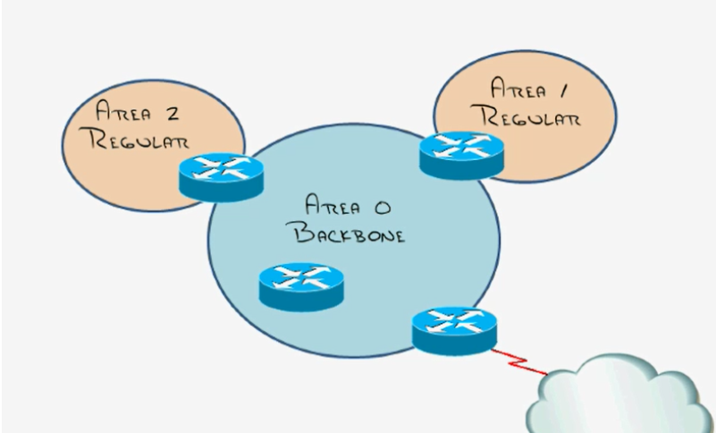
2. OSPF Area Design and Terms
2.1 All Areas must connect to Area 0
2.2 All Routers in an Area have the same Topology Table
2.3 Goal: Localize Updates within an Area
2.4 Requires a hierarchical Design
2.5 Info:
If a network change will occur, only a area will change the topology table. The adjacent area will do nothing with the topology change
in an other area. Example:
Area2 has a change and Area0 or Area Regular will do nothing. It is important to develop a proper area/network design.
Area2: 10.1.0.0
10.2.0.0
10.3.0.0 etc….
Area Regular: 172.16.1.0
172.16.2.0
172.16.3.0 etc….
Area Border Routers (ABR)
The Router with one Interface in AreaX and the other Interface in AreaY.
Autonomous System Boundary Router (ASBR)
Connect outsite the OSPF area’s
ABR and ASBR are the only Routers that have the ability to do summarization.
3. Understanding OSPF Neighbor Relationship
3.1 The Router ID is simply the Router’s name in the OSPF Process
3.2 Highest active interface IP address when OSPF starts
(Loopbacks beat physical interfaces)
This will be the highest active ip address. So this is the routers name.
(RouterID). Loopback address 1.2.3.4 wins against physical interface 192.168.1.1.
It is dangerous to have a changing router ID.
3.3 It is possible to hard-coded the Router-ID using the ’Router-ID command’
3.4 Add Interfaces to the Link State Database
(Dictated by the Network Command)
3.5 Send a hello message on chosen Interface(s)
3.5.1 once every 10 seconds on Broadcast/P-2-P Networks
4 times hello till ospf realized that the neighbor is down. = 40sec.
3.5.2 once every 30 seconds on NBMA Networks (FrameRelay, ATM)
4 times hello till ospf realized that the neighbor is down. = 120sec.
3.5.3 contains all sorts of information
Router ID, Neighbors, hello and dead timers*, router priority, network mask*
DR/BDR ip address, area ID*, authentication password*
*If that not match the router can’t form neighborship.
3.6 Receive Hello
**Init State**
1. check hello / dead interval
2. check netmasks
3. check area id
4. check authentication password
3.7 Send reply Hello
1. Am i listed as a neighbor in your hello packet?
(if yes, reset dead timer)
(if no, add as new neighbor)
3.8 Master – Slave Relationship Determined
**Exstart State**
1. Determinde by “Priority”, Router-ID Breaks Tie
2. Master sends Database Descripiton (DBD) Packet
DBD = Cliff Notes of Link-State Database
3. Slave send its DBD Packet
3.9 DBDs are Acknowledged and Reviewed
DBD (Database Describtion Packets)
**Loading State**
Slave Requests Details (Link State Requests – LSR)
Master sends Updates (Link State Updates – LSU)
Master Requests Details (LSR)
Slave sends Updates (LSU)
3.10 Neighbors are synchronized
**Full State**
Now it’s time to run the DIJKSTRA SPF algorithm to
figure out what to do with all this data
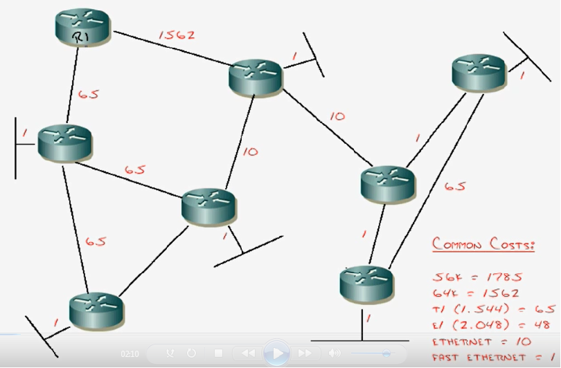
4. OSPF’s Cost
Hint:
EIGRP kept the backup path – OSPF doesn’t.
4.1 Cost Metric
cost = 100 / (Bandwidth in mbps)
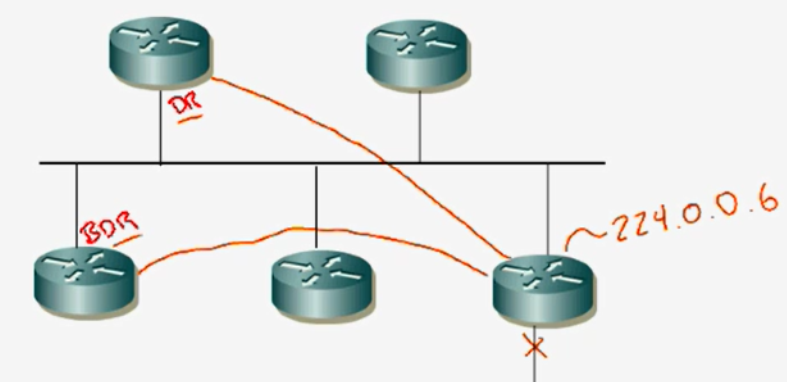
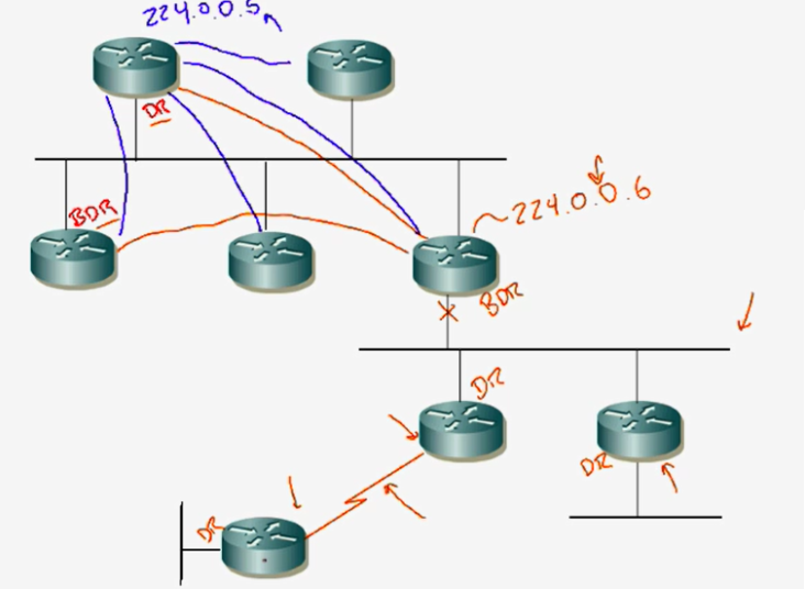
4.2 Understanding the DR and BDR
DR = Designated Router
BDR= Backup Designated Router
DR and BDR listen to the multicast address 224.0.0.6
DR and BDR send updates to all routers with the multicast address 224.0.0.5
DR and BDR are always occur on a shared segment. On point to point links there are
only DR’s and the send the updates only with the multicast address 224.0.0.5
4.3 The Flurry of OSPF Packet Types
1. Hello
2. Database Description (DBD)
When the Slave see an update the slave send a LSR to the Master.
The master send an LSU back.
3. Link-State Request (LSR)
4. Link-State Advertisement (LSA)
In an LSU Packet there are many LSA’s for example 50 Networks.
5. Link-State Update (LSU)
6. Link-State Acknowledgement (LSACK)
Every single step will be acknowledged. So OSPF is a reliable protocol.