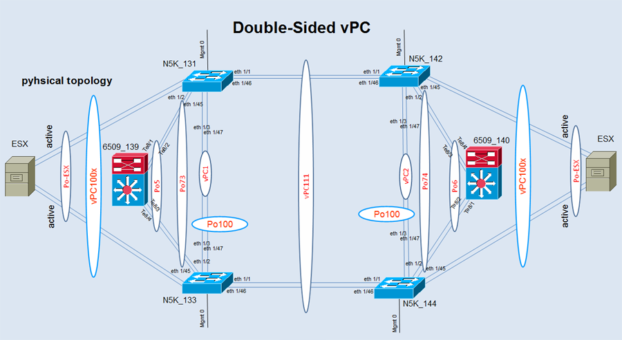
Double-Sided vPC with N5k and Cat6500
1. Introduction
Here i want to explain, how to create a double-sided vpc in an enterprise environment.
A customer of us want to redeploy his ESX Server connection from active-passive to active-active.
In the past the ESX Server were single-sided connected to one of the N5k devices with two 10 Gbit links.
The ESX Server were bundled in a port-channel on both sides. (N5k <-> ESX)
The purpose:
Dual-Homed design. The ESX Server has a four port NIC card inside. Each physical links should be used
to create an active-active environment. At the migration point the technicians thought they have only
to plug-in two new links to the N5k partner. But – no way.
The proper converstion is only possible with the use of a vPC construction/modification.
The N5k with the even numbers are attached in the datacenter 2. and the N5k with the
odd numbers are attached in the datacenter 1. Each datacenter were connected with dark fiber links.
This is the initial position.
2. physical buildup
In the first figure you see the phyical buildup.
3. logical purpose
The aim is to bring all devices together to eliminate a spanning-tree topology without deactive
spanning-tree. Spanning-tree have to be enabled for outage purposes.
4. Components of vPC
The following table lists important terms you need to know to understand vPC technology.
These terms are used throughout this post.
| Term | Meaning |
| vPC | The combined port-channel between the vPC peers and the downstream device. A vPC is a L2 port type: switchport mode trunk or switchport mode access |
| vPC peer device | A vPC switch (one of a Cisco Nexus 7000 Series pair). |
| vPC domain | Domain containing the 2 peer devices. Only 2 peer devices max can be part of same vPC domain. |
| vPC member port | One of a set of ports (that is, port-channels) that form a vPC (or port-channel member of a vPC). |
| vPC peer-link | Link used to synchronize the state between vPC peer devices. It must be a 10-Gigabit Ethernet link. vPC peer-link is a L2 trunk carrying vPC VLAN. |
| vPC peer-keepalive link | The keepalive link between vPC peer devices; this link is used to monitor the liveness of the peer device. |
| vPC VLAN | VLAN carried over the vPC peer-link and used to communicate via vPC with a third device. As soon as a VLAN is defined on vPC peer-link, it becomes a vPC VLAN |
| non-vPC VLAN | A VLAN that is not part of any vPC and not present on vPC peer-link. |
| Orphan port | A port that belong to a single attached device. vPC VLAN is typically used on this port. |
| Cisco Fabric Services (CFS) protocol | Underlying protocol running on top of vPC peer-link providing reliable synchronization and consistency check mechanisms between the 2 peer devices. |
5. Configuration of a double-sided vPC
The next steps show all necessary minimal configuration snippets for the implementation of a double-sided vPc.
Datacenter 1
Datacenter 2
6. Final Statement
For us it was difficult to bring together datacenter1 and datacenter2 in a logical vPC. vPC111 make the most
trouble to come up proper. We tried this on a live system and there are nearly no time for transaction.
One big mistake was to configure the command ‘spanning-tree port type network‘ in the port-channel 111.
The ESX Server respectively the hosts began to flap and we don’t find the reason for this.
After that we attempt to configure the VPC111 (Po111) with the command ‘spanning-tree port type normal‘.
With this statement we were successful and no flapping appears on ESX side.
The vPC domain identifiers also must be different across the 2 data centers
(vPC domain identifier is used as part of the LACP protocol).
If user absolutely wants to use the same domain-id on both vPC domains, then knob system-mac
(under the domain configuration context) must be uses to force different vPC system-mac values.
Required Recommendation:
Always use different domain ID in double-sided vPC topology.


Great info – thank you!
Hi Jacob,
nice write up! but I am confused, for example on N5K_144:
++++++++++ vPC link to N5k133 and N5k131 ++++++++++++
interface port-channel 101 —111 or 101?
description vpc101->Switch 133+131
switchport
switchport mode trunk
switchport trunk allowed vlan 1,2,3,4 etc….
vpc 101 —–vpc 101 or vpc 111?
++++++++++ vPC link to 6509_140 ++++++++++++
6509_140:
N5K_144:
Interface port-channel 101 —po 101 or should be po6?
description vpc74->Po6 Switch 140
switchport mode trunk
switchport trunk allowed vlan 1,2,3,4 etc….
spanning-tree port type normal
vpc 74
Hi,
thanks to find the mistakes in my config.
++++++++++ vPC link to N5k133 and N5k131 ++++++++++++
Of course, the phy. Ports 1/1 and 1/46 have to be combined to the
port-channel vpc111 on both sides. Datacenter1 and Datacenter2.
Port-channel, description and vpc command are the same = 111.
++++++++++ vPC link to 6509_140 ++++++++++++
The port-channel in this case is not 101 or po6.
It has to be the port-channel 74. vpc command points to vPC2 in
Datacenter2.
All mistakes were corrected in this post,now.
Excellent observed
King Regards
Jacob
Do you have any video of that? I’d want to find out some additional information.
Hi Jacob,
-port channel between n5k-131 and n5k-133 is po100
-port channel between n5k-142 and n5k-144 is po100
my question is do the port-channel number have to be the same ?
what if we use different port-channel number like
-port channel between n5k-131 and nk-133 is po100
-port channel between n5k-131 and nk-133 is po300
Does that work ?
thanks
Saul
Hi Saul,
the port-channel numbers don’t have to be identical numbers on both sides for the vpc peer-link.
Only the vpc domains have to be different. vpc1 and vpc2 for example.
http://www.cisco.com/c/dam/en/us/td/docs/switches/datacenter/sw/design/vpc_design/vpc_best_practices_design_guide.pdf
Kind regards
Jacob